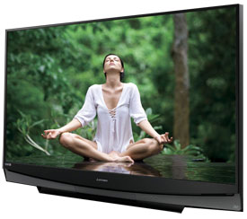
- Mitsubishi Wd 60735 Dlp Chip
- Mitsubishi 60735 Troubleshooting

- Download owner's manuals, software/firmware, product specification and more. Select a Category DLP CRT LCD/LED Plasma LaserVue Accessories VCRs DVDs HDTV Components Documents for model WD-60735.
- Mitsubishi Wd-60735 User Manual View and Download Mitsubishi WD-65000 owner's manual online. Mitsubishi Digital Projection TV Mitsubishi WD-60735 Owner's Manual. Mitsubshi digital. 915B403001 MITSUBISHI WD-65735 WD-60735 TV LAMP WITH HOUSING locate your TV manufacturer's model number from original user manual or off.
- Download owner's manuals, software/firmware, product specification and more. Select a Category DLP CRT LCD/LED Plasma LaserVue Accessories VCRs DVDs HDTV Components Documents for model WD-60735.
Mitsubishi Wd 60735 Dlp Chip
May 30, 2012 Replacing a Mitsubishi DLP TV Lamp - 915B403001 Bulb/Lamp - How to Repair DLP TVs. Video Tutorial how to replace a 915B403001 bulb - Mitsubishi DLP TV. MITSUBISHI WD-60735. MITSUBISHI. 14.43MB MITSUBISHI TV MANUAL WD 60735 As Pdf, TV 60735 MITSUBISHI WD MANUAL As Docx, TV 60735 MANUAL MITSUBISHI WD As Pptx MITSUBISHI TV MANUAL WD 60735 How easy reading concept can improve to be an effective person? MITSUBISHI TV MANUAL WD 60735 review is a very simple task. Choose user manuals and guides to match your own needs. Jan 29, 2018 Amazon.com: TV lamp for Mitsubishi WD-60735 180 Watt RPTV Replacement: Electronics. Skip to main content. Try Prime EN Hello, Sign in Account & Lists Sign in Account & Lists Orders Try Prime. User Manual pdf Warranty & Support Product Warranty: For warranty.
Mitsubishi 60735 Troubleshooting
INTRODUCTION ... 5 Dimensions, weight, power usage, etc. ... 5 PRODUCT SAFETY NOTICE ... 5 SAFETY PRECAUTIONS ... 6 DISASSEMBLY ... 7 Back Cover Removal ... 7 Chassis Removal ... 7 Rear Input Cover Removal ... 8 PWB-POWER Removal ... 8 Chassis Cover Removal ... 9 PWB-HDMI-FRONT Removal ... 9 PWB-MAIN Removal ... 10 OPTICAL ENGINE ... 11 Optical Engine Removal from cabinet ... 11 Optical Engine Removal from Duct Assembly ... 12 Upper Duct Removal ... 12 Lower Duct with Upper Duct removed ... 12 Lower Duct Removal ... 13 Engine Replacement ... 13 Ballast Removal ... 14 SCREEN DISASSEMBLY ... 14 WD-65835 & WD-73835 Escutcheon Removal ... 14 Screen Assembly (Bezel) Removal ... 14 Screen Removal From Bezel ... 16 Screen Replacement. ... 18 Speaker & PWB-SBL Replacement ... 19 Speaker Replacement ... 19 INITIAL SETTINGS, INITIALIZATION & TROUBLESHOOTING ... 20 Option Menu & Remote Control ... 20 Digital Signal Strength ... 20 Reset and Initialization ... 21 Initial Settings ... 22 A/V Reset ... 23 LED Indication Diagnostics ... 24 Error Code Operation ... 25 Color Wheel Replacement ... 26 SERVICE ADJUSTMENTS ... 28 Equipment & Test Signals ... 28 Circuit Adjustment Mode ... 28 Horizontal & Vertical Centering Adjustment ... 28 Manual Keystone Geometry Alignment ... 29 Full Adjustment Mode Activation ... 30 4x3 and Letterbox Alignment modes ... 31 Touch Up Adjustment Mode ... 32 Data Transfer ... 32 USING LEAD FREE SOLDER ... 33 CHIP PARTS REPLACEMENT ... 34 REPLACEMENT PARTS ... 35 Parts Ordering ... 35 Critical and Warranty Parts Designation ... 35 Parts Tolerance Codes ... 35 Quick Reference List ... 36 SERVICE PARTS LIST ... 37 SCREEN ASSEMBLY PARTS LIST ... 43 MIRROR REPLACEMENT ... 44 CIRCUITRY BLOCK DIAGRAMS ... 47 Main Power Supply ... 47 DC to DC Supplies ... 48 Analog Video Signal Path ... 49 Digital Video Signal Path ... 50 Overall Sound Signal Path ... 51 Overall Control Circuitry ... 52 Auto Input/Output Detect Circuitry ... 53 Lamp Control Circuitry ... 54 Short Detect Circuitry ... 55 Engine Protect Circuitry ... 55 System 5 / Wired Remote I/O ... 56 SCHEMATIC DIAGRAMS ...
